After designing a complete 3D model on software like SP3D, PDMS, Autodesk, etc it is important to communicate the same information to the fabrication and construction team with enough clarity. Sometimes it is not possible to convey all the information through a single drawing. To resolve this problem designers developed many other drawings that can collaboratively give the required information to the end-user of drawings.
In process or power piping mostly 05 types of drawings are developed which help the execution person to understand the concept developed by the designer. These drawings give information with help of:
- Schematics drawings
- Drawings describing Basic design basis and
- Specification for piping
In this article, we will explore all those piping drawings that are required to execute piping work.
- General Arrangement Drawing (GAD)/Piping plan drawing
- Process flow diagram (PFD)
- Piping and Instrumentation Drawing (P&ID)
- Plot plan layout
- Piping Isometric drawing
At the end of this article, you will be able to understand and learn the following information about all drawing types frequently used in piping.
- What are these types of drawings drawing?
- What information do we get from each of these drawings?
- What checkpoint we must look for in every drawing?
- Is there any limitation of every drawing? If yes, what are these limitations?
More to Read: What Is RF Pad? How To Calculate Reinforcement pad dimensions?
Table of Contents
Types of Piping Drawing
For planning and constructing a project, we need to refer to multiple drawings to extract all data required. A single drawing is never enough for defining the nature, scope, and layout of a project construction site. The types of piping drawing required are as follows:
- General Arrangement Drawing (GAD) or Piping Plan drawing
- Process flow diagram (PFD)
- Plant and Instrumentation diagram (P&ID)
- Plot Plan
- Piping Isometrics
Brief on GA drawing/Piping Plan drawing/Piping Layout drawing
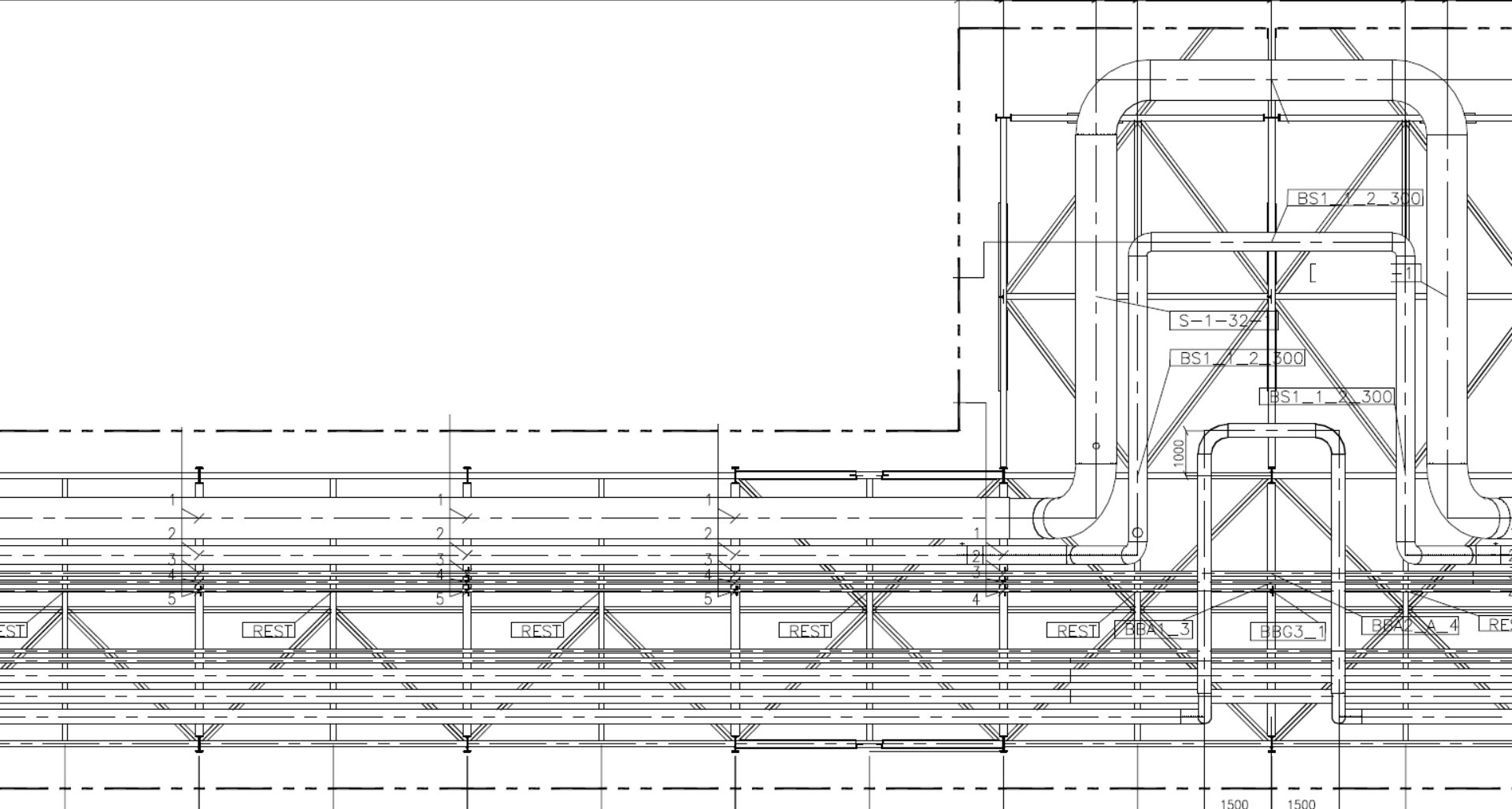
Piping General arrangement drawings or Piping plan drawings of either piping system or equipment are developed by piping designers with the vision of giving clarity of complete assembly of the piping system.
These drawings represent the main dimension of the piping system using a 2D view of Top and side interface and sometimes the front view too. that’s why sometimes a piping GA drawing is also referred to as a piping layout drawing.
Piping GAD describes a piping arrangement in the plan as well as an elevation view. The plan view is a sectional view of elevation GAD, for each elevation, there is a separate plan view representing all required information for that cut section.
All necessary details like support, the line-to-line distance, the layout of the line, the position of line w.r.t to a civil structure. For a greenfield engineering project, the equipment location needs to be fixed at the time of proposal. On starting of project work this drawing is useful as the basis for developing the piping base layout.
Depending on the requirement and feasibility of piping layout arrangement piping GAD gets revised and updated. The changes to equipment location require a necessary transition in order to have desired piping arrangement. A piping GAD depends on some reference source developed prior to piping arrangement work. And after some desirable level of development modification is required to those references to get the required piping layout arrangement.
Some terminology frequently used in Piping GAD are:
There are some legends or terminology that you must know while reading piping GAD:
- Battery limit: It is defined as the boundary of plant area. The complete project is limited to execute within the battery limit.
- Drawing Limit: This gives an indication about the limitation of that specific GAD. This is drawn with bold dashed lines around the drawing sheet.
- Match Line: This line can be defined as connections between two battery limits. Match lines are shown with coordinate in a horizontal plane and with Elevation in a vertical plane.
- Equipment: Vessels, Heat exchangers, Pumps, Columns, and other equipment is relevant to this category.
- Piping: A connecting line from one piece of equipment to another is called piping.
- Plant Area: The total project area is defined as a plant area where all required equipment and piping assemblies are located.
- Offsite: Any other area except plant area is referred to as offsite. Offsite is also a part of the plant but it is for auxiliary services like tankage area, cooling towers, chimney, flare exhaust, storage, etc.
- Floor Penetration: When a line travels vertically through a floor GAD shows this as floor penetration.
Information we gain from Piping General arrangement drawing/Piping Plan drawing
Some specific information we can get from piping GAD is as follows:
- Dimensions of pipe length and its route.
- Centreline distance between the line to line.
- The exact position of the pipe assembly on the pipe rack or unit.
- Type of supports required in the pipeline.
- Instrument and equipment connected to the piping.
Limitations of General arrangement drawing/ Piping Plan drawing
Unlike every drawing, piping general arrangement drawing has also some drawbacks and limitations. Those limitations of General arrangement drawings are as follows:
- This drawing doesn’t give details on the type and thickness of insulation.
- This is not helpful with design data like design pressure, design temperature, operating pressure and temperature, Hydrotest (HT) pressure.
- This drawing seems very cumbersome in the case of a dense network of piping.
- When pipe route change after traveling in vertical upwards or downwards position. Sometimes it is impossible to get the exact elevation of the line at that specific point.
- From GAD we won’t get any information about rolling angle when there is some non-conventional change in direction.
Checklist for General arrangement drawings
The following data must incorporate within the General arrangement drawing before issuing this to the end-user for construction:
- Drawing title block, Project Name, Pipeline numbers, and Reference drawing numbers.
- coordinates, Elevation, and the dimension of the pipe.
- North arrow orientation, the direction of flow, and Line continuation details.
- Equipment, valve, and instruments location.
- Battery Limit, Drawing Limit, and match line details.
- Floor penetration, and the orientation of valve.
- Electrical and instrumentation cable tray and Junction box.
- Operational space, overhead clearance, and manway clearance.
- Platforms and walkways.
- Space for Future scope of piping and equipment.
Featured Post: Piping Supports: Types, Codes, Design, Selection, Working, Installation
Brief on Process flow diagram (PFD)
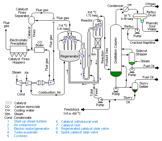
A process flow diagram or PFD is a typical flow diagram that explains relationships between major equipment of a plant. It is most often used in chemical and process engineering to get information on fluid flow direction and connectivity between different equipment through the piping system. PFD helps to understand the chemical process, provide quality control and increase efficiency.
A process flow diagram is used to get start to end understanding of how different types of equipment and chemicals work together in the process plant. PFD maps various tasks and helps you to understand which task is most important that needs to be done repetitively to perform to achieve some specific product.
PFD helps to understand the process, provide quality control, and increase efficiency. It is used to get a top-down understanding of how different types of equipment and chemicals work in the industrial plant. It maps various tasks and shows what repeatable tasks you may need to perform to achieve a specific goal.
Terminology frequently used for PFD
Here is a list of some typically used term which is frequently used in the process flow diagram:
- Major Equipment: This includes Name and Tag numbers of equipment that has a major role in the plant. For example Pumps, Vaccum column, Crude Column, Compressors, Boilers, coolers, mixtures, etc.
- Process pipings: This is the network of pipes that transport fluid from one piece of equipment to another.
- Flow direction: This provides information about the direction of the flow of fluid. i.e. from which equipment fluid is taken the exit and make an entrance.
- Bypass system: This gives inputs about the alternate piping system to be used in case of any maintenance or shutdown.
- Operational data: This includes pressure, temperature, the volume of fluid, density, mass-energy balance, and mass flow rate.
Information we gain from the Process flow diagram
A typical PFD always gives information like:
- This indicates the capacity and operating information of the equipment.
- for all process flow streams shown on PFD, this gives a unique identification number. This identification number helps to get information about in and out of fluid in any equipment.
- all control valves and process critical valves are indicated in PFD.
- if there is any other system is connected with the main piping system, It is indicated in PFD.
- Composition of fluid in a system
Limitations of Process flow diagram
There is something that must not be included in a process flow diagram and henceforth we can get this information from PFD.
- Pipe class and isometric numbers.
- Piping code information.
- Instrument tag numbers.
- Minor bypass system and valve stations.
- Maintainance drain and vents.
- Pressure relief and pressure and pressure safety valves.
Checklist for Process flow diagram
before issuing a PFD to the process team following things must be check:
- Drawing number, page number, Latest revision, and revision purpose.
- Stream data table. e.g. correct units for measurement, flow rates
- Equipment tags correctly formated, well placed, and match with P&ID.
- Instrument type and logic must be shown correctly.
- in case of any revision, old and new line numbers must be differentiated correctly.
Brief on Piping and Instrumentation Drawing (P&ID)
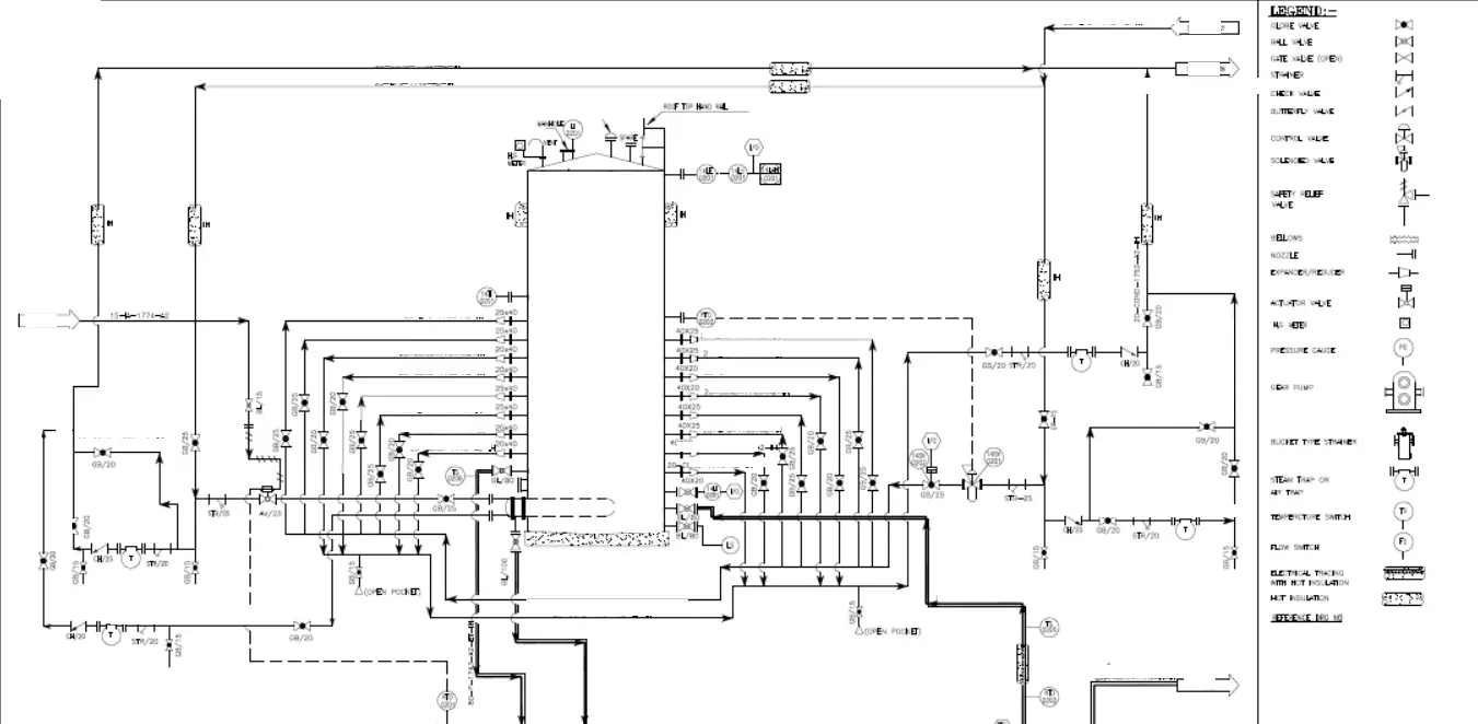
Piping and instrumentation drawing (P&ID) is also known as Process engineering flow schemes (PEFs). At first look, you may find PFD and P&ID similar but both have huge differences from each other. P&ID is more detailed compare to PFD.
P&ID is a single-line schematic diagram that incorporates all equipment, instruments, valves, line size, and pipe specifications to give us the necessary information.
P&ID is considered the most important document that controls all other related engineering drawings. A P&ID shows all piping networks including the exact physical sequence of branches, reducers, valves, instruments, types of equipment. A P&ID can be used to operate a complete piping system, as it gives information on piping with process flow and installed equipment and instrument with it.
Information we gain from P&ID
The following list will give you an overview of the information we obtain from P&ID.
- Line number, Line size, and Specification of the piping system.
- Name and number of all equipment.
- Type of valve and identification of any special type of valve.
- Details about High point vent (HPV), Low point drain (LPD), Special fittings, sampling points, reducers, spectacles, blinds, etc.
- The flow direction of lines.
- Change in the spec in any line or spec break of a piping system.
- Equipment to equipment connection details.
- Instrument name and number in a piping system.
- Insulation or Jacketing requirements.
- Information of slope data if applicable for any line.
Limitations of P&ID
Although P&ID is much useful and basic drawing for any process plant. It has some limitations and these limitations make this useless in the stage of construction of a project. Some inherent limitations of P&ID are as follows:
- As P&ID is not drawn on a scale it is unable to give you the exact dimensions of any piping system.
- Process condition, Operation condition, and Physical data can’t be obtained from this.
- Equipment location can’t be determined with help of P&ID.
- Line route, length, and fittings in use for the piping network can not be determined.
- Support and structural details are out of the scope of this drawing.
Checklist for P&ID
Going through a checklist before publishing a document is always a good option. In the case of P&ID, It is true as well. The checklist for P&ID is as follows:
- Contractor, PMC, and client details must be on P&ID.
- Drawing number, Revision number, and sheet number.
- Title block including By/Approved/Checked blocks filled and signed, Date, Rev. all company logos, client signoff.
- All equipment incorporated in P&ID must have the correct name and Tag number.
- Battery limits must be marked.
- Change in spec or spec break should be highlighted.
- Line arrow, flow direction, and connecting arrow must be clear and visible.
- Position of spectacle blind much as per process requirement.
- Any special note regarding any HOLD must be specified.
- It must match the process flow diagram correctly.
Featured Article: Crude Oil desalter: Purpose, Working, Types, Parts, variables
Brief on Plot plan Layout
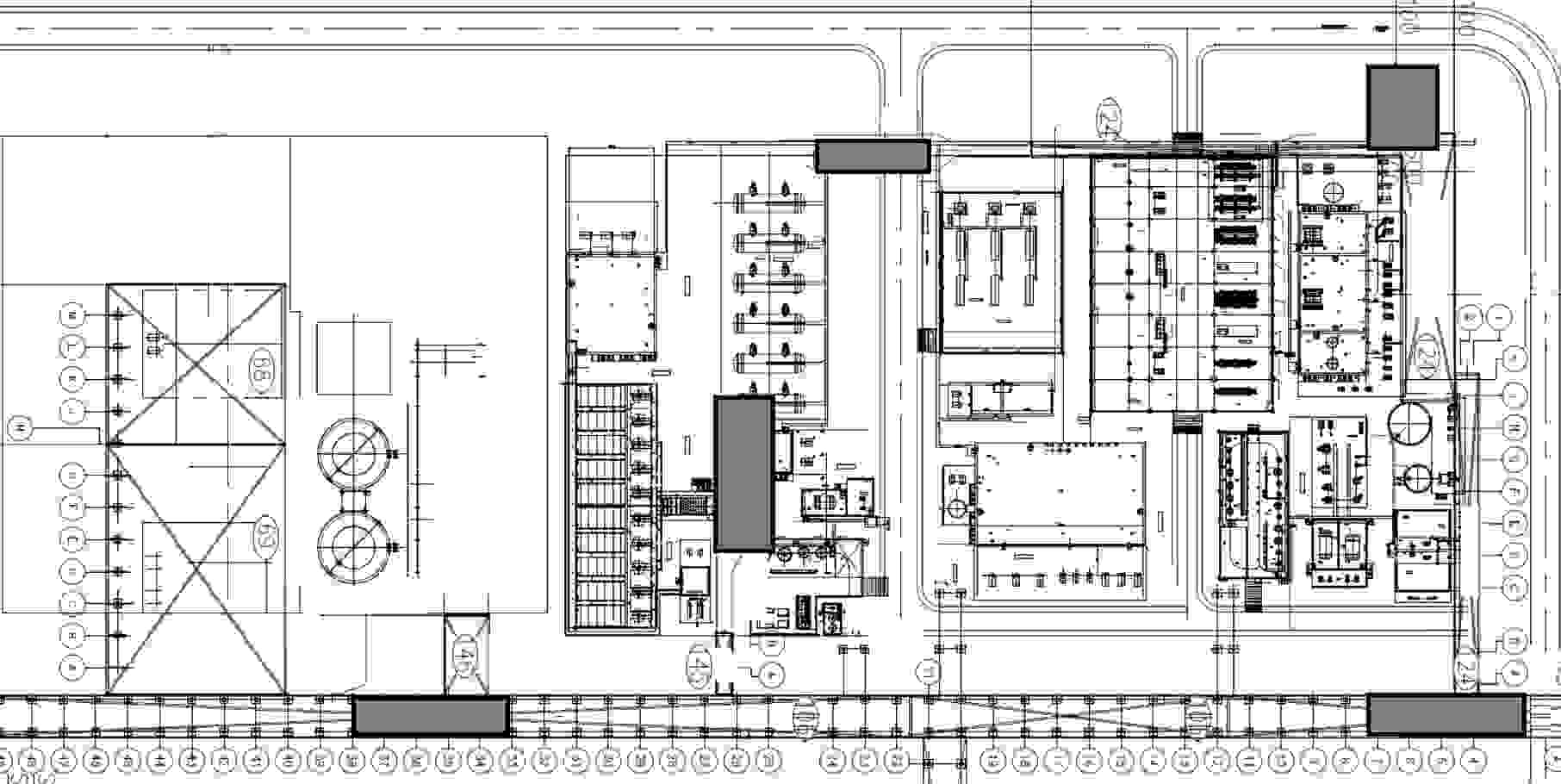
A plot plan is basically an arrangement drawing where all equipment and its supporting facilities like pipe rack, structure, buildings, roads are shown within the battery limit. All equipment and its components are shown on a plot plan are identified by its tag number mentioned in the Equipment index part of the drawing.
Plot plant is drawn is an on-scale drawn drawing. You can imagine that a whole process plant can not be given on a readable drawing. Therefore, a distinction is made, and the plot plan is categorized into two parts.
- Overall Plot plan: A overall plot plan also know as a site plan or site master plant. You can compare with a city road map where all important buildings, parks, and street names are given but not any house number or any details about each building. Here you can locate a tank farm or a unit in that process plant. But it won’t be possible to locate a specific pump with help of the Overall plot plan.
- Detailed plot plan: On the contrary with the overall plot plant, a detailed plot plan gives an overview, i,e, Top view of some parts of the process plant. A major advantage of a properly detailed plot plan is that you can even locate a small filter on that.
Information we gain from the Plot plan layout
The main purpose of the plot plan layout is to show the exact way the intended land is going to use and the equipment position determined. The information we can get from a plot plan drawing is as follows:
- This gives the total area detail of the process plant.
- A plot can give an exact location of all major equipment and important building like compressor area, pump house, refrigeration unit, CDU/VDU column.
- A plot plan drawing can help us to identify the total equipment to be installed in the facility.
- From this drawing, we can determine the length of the pipe rack and the area of each unit in the total process plant.
- This gives details about the battery limit of the process plant.
Limitations of Plot plant layout
Yet plot plan is helpful with representing all important equipment located in a single drawing but this fails to provide some other essential data as follows:
- As the plot plan is a 2D plan view, this fails to provide and elevation details about the plant.
- This fails to provide the location of each and every equipment to be installed in every unit.
- this has no connection with P&ID, PFD, or Isometric. So, with help of this, you won’t be able to judge the piping job in that process plan.
- this doesn’t provide piping system layout, flow direction, or any measurement of piping.
Checklist for Plot plan layout
Before finalization of plot plan, few things that must check are as follows:
- Is this covering any future scope of the place as per the requirement of a project?
- Does this show plan north and true north. And the difference in angle between both.
- The datum point is defined and located on the plan layout.
- Coordinate gridline is shown or not along with Northing/Easting values.
- An emergency exists and assembly points are shown.
- Availability of access for the heavy vehicles for any erection purpose or maintenance is checked or not.
- All units/areas located with respective area code, name, tag.
- Distance between units is mentioned.
- The total equipment list is given in the plot plan layout.
- All symbols provided are as per applicable standard legends.
- Drawing standard is compatible with project specifications and company standards?
- Drawing title, Drawing number, and project details.
- Revision clouds along with revision triangles
- Hold clouds if applicable somewhere.
- Status stamp. i.e. for approval or for construction
Brief on Piping Isometric drawing
Piping Isometrics provides us complete details of pipe route, Dimensions, all technical data required for project execution, and details of Support attached to that piping network. Piping Isometric drawing is not on-scale drawing. It is a single line diagram with details of:
- Type of joint i.e. Butt, Socket, or Thread.
- Scope of joint in field of the fabrication shop.
- Piping components, Support details, Equipment connections, and any special item connected to the piping system.
This piping isometric drawing is useful for each and every person connected with the project. For e.g. :
- For fabrication: To fabricate spools
- Planner: To extract essential data for smooth planning and execution.
- Site Engineer: To Plan job as per priority, Erection of spool, Alignment, and Supporting.
- Procurement Team: To extract MTO for required material in the project.
- Billing Team: For the preparation of a bill to claim.
To Know more about Piping Isometric, please follow our this Article Specially written about Isometrics
Checklist for Piping Isometric drawing
Unlike all other drawings, checking of Piping Isometric Drawing before the final release is the most important thing from a construction point of view. A correct error-free Piping isometric improves quality and saves time on the job. Most of the design companies follow a checklist to help Piping isometric checker. This checklist contains the following important points to look for:
- North direction markup
- Line numbers and Line specification
- Start and Endpoint of Isometric with proper connecting details, coordinates, and Elevation
- Branch connection and other tapping points if applicable.
- Flow direction
- Correct symbols for applicable fitting in isometric.
- Support location and Its tag numbers.
- Insulation details; If applicable.
- Flow direction.
- Instruments and Equipment tag number and connection details.
- High point vent and Low point drain for Hydrotest purpose.
- Details of Piping component its tag number, Size, specification, and standard codes.
- Slope or free-draining requirements.
- Drawing details of P&ID and GAD numbers.
- Details of any removable spool for maintenance purposes.
- Any special requirement of the piping system.
- Special piping components with Tag number and description.
- Special notes for stress critical lines.
- Status of Isometric. i.e. In Review or Released for construction
- Latest revision number and cloud marking on changes from last revision.
- The requirement of electrical tracing.
Difference Between GA and P&ID
| GAD | P&ID |
|---|---|
| This gives the actual direction of piping arangement | Piping direction and layout can’t be determined with help of P&ID |
| Various information about dimensions can be obtained | No information about dimension |
| Equipment nozzle details can’t be obtained | All details about piping to equipment connection are present |
| Gives info about Support type to be installed | No information about support |
| We can prepare piping MTO from this | Material requirements can’t be fixed |
| The exact position of the pipe on the rack or unit can be determined | This doesn’t give any information about the positioning of pipes |
Conclusion
Yet all drawings are not in use at the same time but sometimes all those drawings need to bring together for better clarity and understanding of the piping system in the process plant. From the above article, we can conclude the following things for a better understanding of this article.
- A piping isometric drawing is co-related with P&ID, GAD, and PFD.
- Piping Isometric is not drawn on a scale.
- P&ID is a schematic diagram that gives information about the piping system connecting from one equipment to another and its flow
- PFD or process flow diagram tells us about state and chemical process details of the main equipment installed in the plant.
- General arrangement drawing or piping plan drawing is given a top view of the piping layout and provides all required dimensions required for piping erection.
- The plot plan gives you all details about every important equipment and unit of the plant. this drawing is drawn on the scale.
- There are some terminologies used for each drawing that we must know.
- Information we can gain from each type of drawing and its importance.
- There is always some limitation of each drawing that’s why we need to look for another drawing for better clarification of the piping system.
- Checklist for each drawing before releasing drawings for construction.
