In industries, a system of pipes and other connecting fittings, valves, and special items is used to convey fluid from one point to another. In general, you can compare this with a water pipeline installed in your home for water distribution from Tank to your washroom, Kitchen or Handwash. However, Piping is a much vast subject than that water pipeline installed in our home.
Table of Contents
What is Piping?
Generally, most people are familiar with plumbing as it constitutes water transportation in every home.
Piping can be defined as:
Interconnected Pipes subjected to the same set or sets of design to fulfill the purpose of fluid transportation using different flow control and measurement methods.
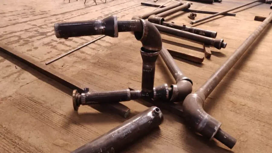
Piping also contains many different types of components like:
- Pipe fittings, eg. Elbow, Tee, Reducers, Flanges, couplings etc.
- Valves, eg: Gate valve, Globe valve, Ball Valve, Butterfly valve, control valve etc.
- Instruments, eg: Pressure indicator, Temperature indicator, Flowmeter etc.
- Equipment, eg: Pumps, Vessels, Heat exchanger, Ejector etc.
More to Read: An Overview on Different type of piping drawing used in Piping Project Construction
What is Pipe?
The main part of any piping system is Pipes which are used to convey materials. Pipes can be defined as: “A metallic or non-metallic cylinder used to convey fluids or transmit fluid pressure.” A pipe is normally a tubular section but its shape is not restricted to a circle. Pipes are made out of Metals, Ceramics, Plastics, concrete, and fiberglass.
Typically metal pipe is made of Steel or Iron such as Carbon steel, Stainless steel, galvanized steel, ductile iron, brass, and alloy steel. Used of different metal pipe are designed as per pressure and fluid flowing through it. There are some terms related to pipes that are important to know by all piping engineers. Generally Pipes for any pipe system to be used as per design and Piping standard codes.
1. What is Nominal Pipe Size (NPS)?
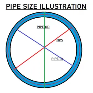
Pipe size is measured with this unit. A 4-inch pipe has never a dimension of 4 inches. Instead, its outer diameter is fixed at 4.5 inches and the inner diameter can vary depends on the thickness of the pipe. Nominal pipe size is neither OD nor ID of pipe. Manufacturing of NPS 1/8 inch to NPS 12″ pipe is done with a fixed pipe outside diameter. So, any increase in wall thickness is resulted in to decrease in Pipe inside diameter.
Manufacturing of NPS 14 and above size pipe, OD has the same value of Nominal size of the pipe. For example, a 16″ NPS pipe will have an OD of 16″ only.
Table for Pipe Outer diameter
| SL. NO. | Nominal Pipe Size | Outer Diameter | ||||
|---|---|---|---|---|---|---|
| Inch | mm | Inch | mm | |||
| 1 | 0.5 | 13 | 0.84 | 21 | ||
| 2 | 0.75 | 19 | 1.05 | 27 | ||
| 3 | 1 | 25 | 1.315 | 33 | ||
| 4 | 1.25 | 32 | 1.66 | 42 | ||
| 5 | 1.5 | 38 | 1.9 | 48 | ||
| 6 | 2 | 51 | 2.375 | 60 | ||
| 7 | 2.5 | 64 | 2.875 | 73 | ||
| 8 | 3 | 76 | 3.5 | 89 | ||
| 9 | 3.5 | 89 | 4 | 102 | ||
| 10 | 4 | 102 | 4.5 | 114 | ||
| 11 | 4.5 | 114 | 5 | 127 | ||
| 12 | 5 | 127 | 5.563 | 141 | ||
| 13 | 6 | 152 | 6.625 | 168 | ||
| 14 | 7 | 178 | 7.625 | 194 | ||
| 15 | 8 | 203 | 8.625 | 219 | ||
| 16 | 9 | 229 | 9.625 | 244 | ||
| 17 | 10 | 254 | 10.75 | 273 | ||
| 18 | 11 | 279 | 11.75 | 298 | ||
| 19 | 12 | 305 | 12.75 | 324 | ||
| 20 | 14 | 356 | 14 | 356 | ||
NOTE: This is to note that after 14″ pipe size, its outer diameter and NPS have the same value.
2. What is Pipe Nominal Bore (NB)?
NPS is a frequently used term for referring to the size of a pipe. Basically, there is no difference between NB and NOS. NB is just an American way to refer to pipe size.
3. What is pipe DN (Diameter Nominal)?
DN or Diameter Nominal is an International indication and also the European equivalent of NPS to indicate pipe size. Here you have to note that DN is the way to indicate pipe size in “mm”. For example, 4″ pipe is simply mean as DN 100
4. What is Pipe Schedule?
The unit of wall thickness measurement for a pipe is “Schedule“. This is the standard method to define the thickness of pipe in the process plants. To simplify the piping thickness indication system ASME (American Society of Mechanical Engineers) committee has developed a “Schedule Number” system based on modified Barlow’s wall thickness formula.
Schedule number = P/S
- P is the service pressure in (psi)
- S is the allowable stress in (psi)
So, what does Schedule 80 means?
Schedule 80 is nothing but a pipe thickness indicator. In simple words, You can say that for a given material schedule 80 pipes can withstand a certain amount of pressure and stress.
In general, you can Download a very useful application for all Pipe and Fittings related data from Google Playstore.
What is Piping Isometric Drawing?
To know about piping isometric drawing you have to first know, What is Isometric Drawing?
If you are from an engineering background then I hope you must have learned to draw Orthogonal projection of any object. Isometric drawings are the representation of the 3-D object in a 2-D plane. Isometric drawing is basically an Axonometric projection in which three co-ordinate systems appears in the same plane 120 degree apart.
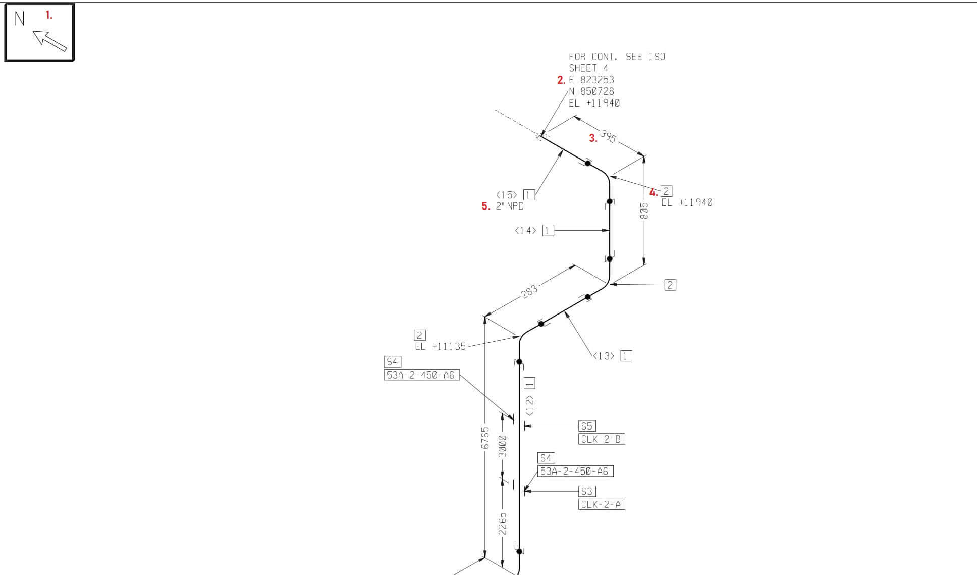
Isometric drawing can provide you details about the movement of the pipe mainly in Three directions. i.e. 1. East-West 2. North-South 3. Up-down. Apart from the mentioned three directions, isometrics can Even represent a line that is leading other than these three directions. i.e. E-S direction, N-W direction, N-Up direction etc.
From the above image, you can find some information to start your journey towards piping. Please look for Red color numbers in the image for reference.
Point no. 1: This represents the direction of isometric drawing.
Point no. 2: This represents the co-ordinate of pipe from datum point. This Includes Northing, Easting, and Elevation of a Pipe as per design.
Point no. 3: This gives you the length of the Pipe running in a specific direction.
Note: Please keep in mind that any dimension given in isometric is from the center to center dimention.
Point no. 4: This gives you a notation of the item used.
Point no. 5: This will provide you information regarding the size of the pipe to be used.
Isometrics drawing are not drawn in scale. These are dimensioned and directional drawings for a process line. Pipes are shown here as single lines and symbols are used to represent Pipe fittings, Valves, Pipe weld, etc.
How Pipe description is written in Piping Isometrics?
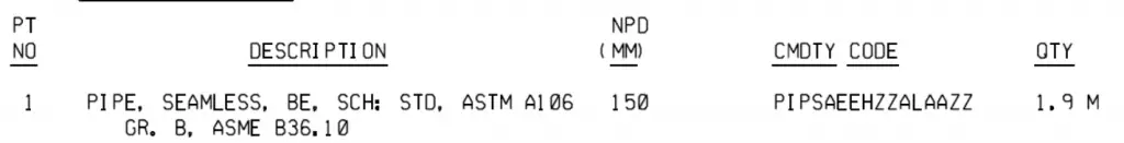
The description given in the isometric drawing can tell you all about the pipe going to be used for the fabrication of spools. From the above image, the Description of the pipe can be briefed as:
SEAMLESS: The pipe that will be used must be a seamless pipe.
BE: Received full-length pipe will have a beveled edge for joint preparation.
SCH STD: Indication pipe schedule to be used. In this case, SCH standard pipe will be used.
ASTM A106: This defines the material grade and composition of the pipe as per ASME standard B36.10
What is the Difference between Piping and Plumbing?
While Piping and plumbing share many similarities the ultimate difference lies in the purpose of the piping system and plumbing. To know if it is piping or plumbing you have to determine by examining the pipe and its connected endpoints. i.e. From where it is connected and where the fluid goes.
- The plumbing system transports water into facilities and provides safe drainages for water and wastewater.
- A piping System moves chemicals, gases, water, and many other fluids to support a system of manufacturing or processing operation.
What is SRL and DRL?
In piping engineering, SRL and DRL stand for “Single Random Length” and “Double Random Length” respectively. These terms are used to specify the standard lengths of pipes.
- Single Random Length (SRL): This refers to pipes that have a random length typically ranging from 16 to 25 feet (4.8 to 7.6 meters). The exact length can vary based on the manufacturer, but it’s usually within this range. SRL pipes are commonly used for various industrial applications where specific lengths are not required.
- Double Random Length (DRL): DRL pipes are twice the length of SRL pipes, typically ranging from 32 to 40 feet (9.6 to 12.2 meters). Similar to SRL pipes, the exact lengths can vary based on manufacturer specifications. DRL pipes are often used in applications where longer lengths are needed to reduce the number of joints and connections, which can help improve the overall integrity and strength of the piping system.
Both SRL and DRL pipes are widely used in various industries such as oil and gas, petrochemical, power generation, and construction. The choice between SRL and DRL pipes depends on factors such as project requirements, transportation considerations, and installation preferences.
Conclusion
- A Piping system is an assembly of pipes, fittings, valves, and other piping components installed to move chemicals, gases, and many other fluids from one place to another.
- Pipes are the principal part of a piping system in the shape of a cylinder.
- The size of a pipe is represented as NPS and its thickness as Schedule.
- Piping Isometric drawings are a representation of 3-D projection in a 2-D plane.
- Description of pipe in piping isometric gives information above pipe type, its material, end edge type, thickness, and code to follow.