In our last article of What is Piping, we gave you a summarized understanding of Piping Isometric Drawings. Here we will focus on getting familiar with Piping isometrics. From understanding what Piping Isometric drawing is to Obtaining knowledge of Reading it in the most appropriate and easy manner. For reading any Piping isometric drawing you must have to familiar with these 04 important things:
- Co-ordinate System
- Piping Symbols
- Understanding of Directions
- Pythagoras Theorem (For Rolling movement of Pipe)
Let’s first focus to know what is a piping Isometric? Which will help you with the fabrication and Erection of the pipe in its proper location.
More to Read: What Is RF Pad? How To Calculate Reinforcement pad dimensions?
Table of Contents
What is Piping Isometric drawing?
After establishing a 3-D model in PDMS, SP3D, or any other software, Piping designers have to communicate the same information to the person who is executing that piping job either in the yard for fabrication or in the field for Erection/Construction. The conveyed information must be enough for the execution person. So that, they can understand well and get a vision of the fabrication of Spools and how the piping is connected with other equipment or special items.
Here comes the role of Piping Isometric drawing. This kind of drawing helps a designer to transfer his vision of piping connections to the team executing construction projects. Piping isometric is a representation of a single pipe line in a process plant with exact dimensions and Bill of Material (BOM). It is the most important deliverable of any project where piping plays a vital role.
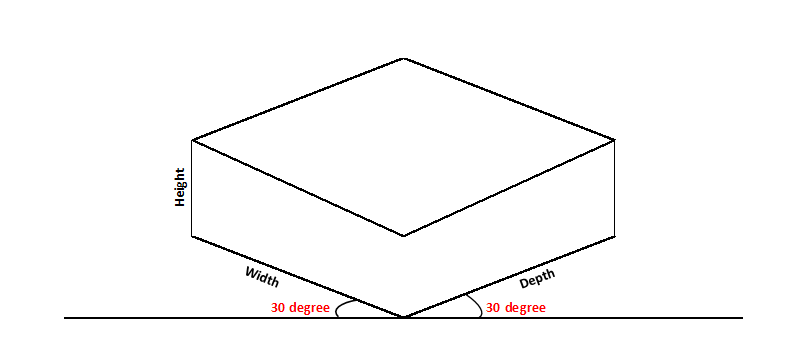
By Definition, Isometrics drawings are a graphic representation of a 3D routed line in a 2D plane that combines height, length of pipe in a single drawing with a 30º angle on both sides from horizontal.
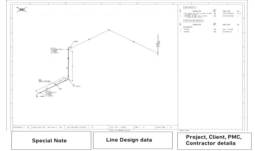
The main body of a piping Isometric drawing is consist of:
- Line Number
- Flow direction
- Piping components
- Weld joint type and its location
- Continuation isometric number
- Co-ordinates and Elevation of Pipe
- Connection details with equipment
Section of Left or right of Piping Isometric drawing includes:
- Piping component description
- Material code
- Nominal size of components
- Quantity of components
- Whether a field or shop item
Bottom Section of Isometric Drawing contains:
- Project name, Client, PMC ( Project management consultancy), and Contractor details
- Pipe line details i.e. Line number, Line size, fluid code, Design, and operating temperature, and Pressure
- Piping class, Inch-Meter, Inch-Dia
- Special notes created for any drawing. i.e. Stress criticality, Heat expansion, etc
Calculations for Piping data from Isometric drawing
- Inch Meter: Length of pipe (in meter) x Size of pipe ( in inch )
- Inch Dia: Size of Pipe joint ( in inch) x No, of Joints
- Insulation Area (in m²): [π(Pipe OD+ insulation thickness)] (all in meter) x Length of Pipe ( in meter )
- Weight of Pipe: π x diameter of the pipe (in m) x length (in m) x thickness (in mm) x density of pipe material.
Density of CS = 7.85 g/cm3 - The volume of Water required for hydro testing: π x {Pipe ID (in meter)}² x Length of Pipe
More Resources: Heat Tracing in Piping: Types, Working, Use, Installation, Comparison (Steam Tracing vs Electrical Tracing)
Features of Piping Isometric Drawings
Isometric drawing is a 2D drawing that enables a person to get a vision of a 3D view of a line. Some important feature of any piping isometric is as follows:
- All isometric drawings are prepared irrespective of Line length and size as well as piping components but this gives the exact dimension of everything mentioned in the drawing.
- The line diagram shown in the isometric drawing can’t define line size. Actual line size can be obtained from BOM or NB (nominal bore) mention in isometric.
- This can also represent a line which not traveling in the exact North, south, east, west, up, or Down direction.
- This can indicate the type of joints to be done among piping components that will be used.
- This can give you fluid flow direction, Equipment connection details, and a special item attached to it in a single plain.
More Resources: An Overview on Different types of piping drawing used in Piping Project Construction
The coordinate system of Piping Isometric
If you are a science student then I am sure you have learned about coordinate systems. Yes…!! the same coordinate system which works on three Axis. i.e. X-axis, Y-axis, Z-axis. To learn about coordinate systems you have to just modify your concept up to some extent.
Here you have to keep 03 important points in your mind always while reading Piping isometrics:
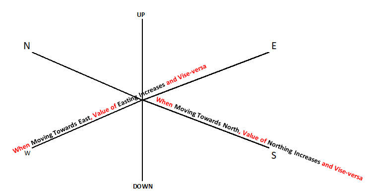
- Value of Northing or Easting always increases while a pipeline moves in that direction and Vice-versa. For Example: Consider at some point Northing of Pipe’s face is N 524.196 and the pipe traveled towards the south by 10.94m then the current coordinate of that point will be, 524.196-10.94=513.256 (Value of Norting after line movement).
- When Line moves in East or West direction only, Value of Northing doesn’t change.
- If the Line is moving in an upwards or downward direction then the Northing or Easting of that point doesn’t change. There will be an effect only on the value of Elevation.
Now take a quiz to check what you have understood from this section

Features of Piping coordinate system
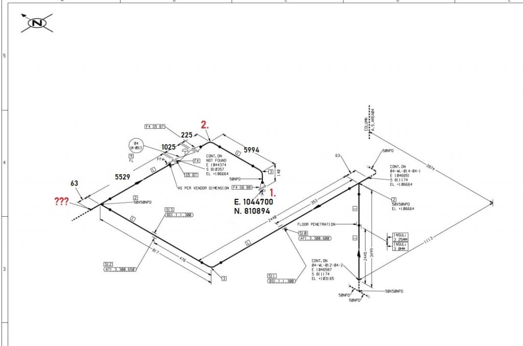
As we already know, Piping isometric drawing is drawn to scale. That’s why calculating various data from an Isometric coordinate system is required. The Isometric is commonly referred to as oriented towards the North direction marked with an arrow in the top right corner. With help of the coordinate system in Piping isometric drawing,
- Length of Pipe can be calculated by subtracting Two Northing, Two eastings, or Two elevation values.
- The coordinate system helps to gain a vision as isometric drawings are not on the scale.
- This helps to get Northing or Easting point of any point in between the line.
- Can calculate the exact location of the pipe line in a unit or Pipe rack.
- Gain information about the equipment nozzle to which pipe is going to be connected.
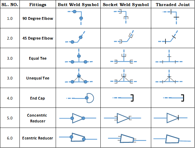
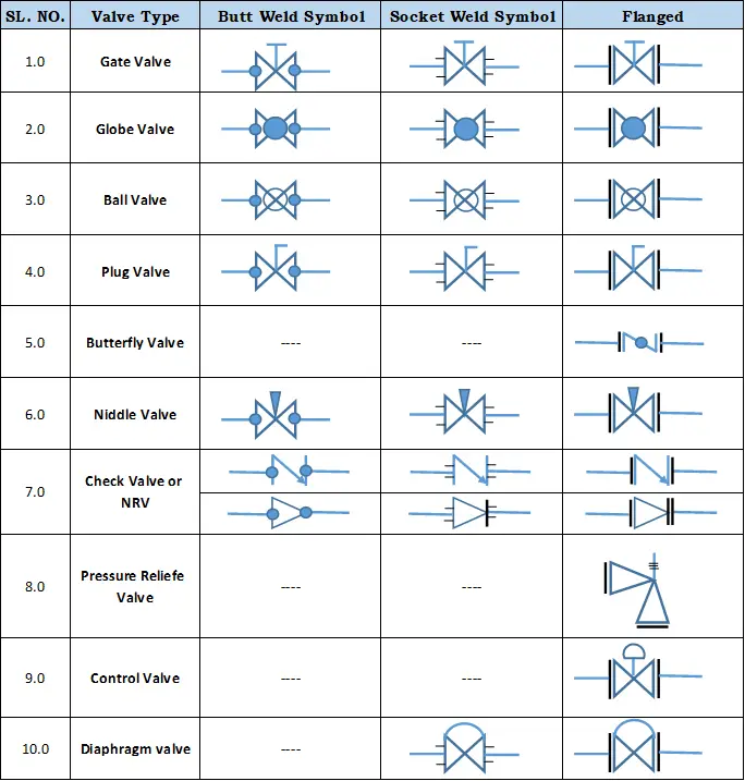
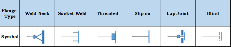
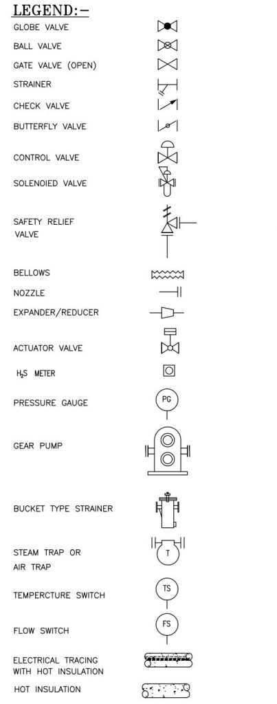
Piping Symbols for Isometric Drawings
Knowing legends and symbols that are universal for reading a Piping isometric drawing is much helpful to gain info about the Piping material or piping fittings that are going to be used for fabrication or construction work. Knowledge of symbolic representation of piping is helpful to gain quick knowledge with observing BOM. Yes, you will still need to read BOM to know the Pressure rating and MOC of pipe fittings and components.
Feature of Piping Drawing symbols
- This gives you a quick detail about the type of joint, ie. Buttweld, socket weld, or Threaded join between the fitting.
- Piping symbols are a quick reference to know about the type of fitting and component to be used.
- This gives you knowledge of the type of Valves to be in-line with piping isometric.
- Any instrument attached to a piping system can be easily known with reference to piping symbols.
- With help of piping symbols, we can know about the equipment connected with piping symbols.
Piping Symbol chart for Piping Isometric or P&ID
Pipe Fittings Symbols
Valve Symbols
Piping Flange Symbols
Miscellaneous Piping Symbols
Click here to Download Piping Symbol Pdf
How to Read Piping Isometric Drawing?
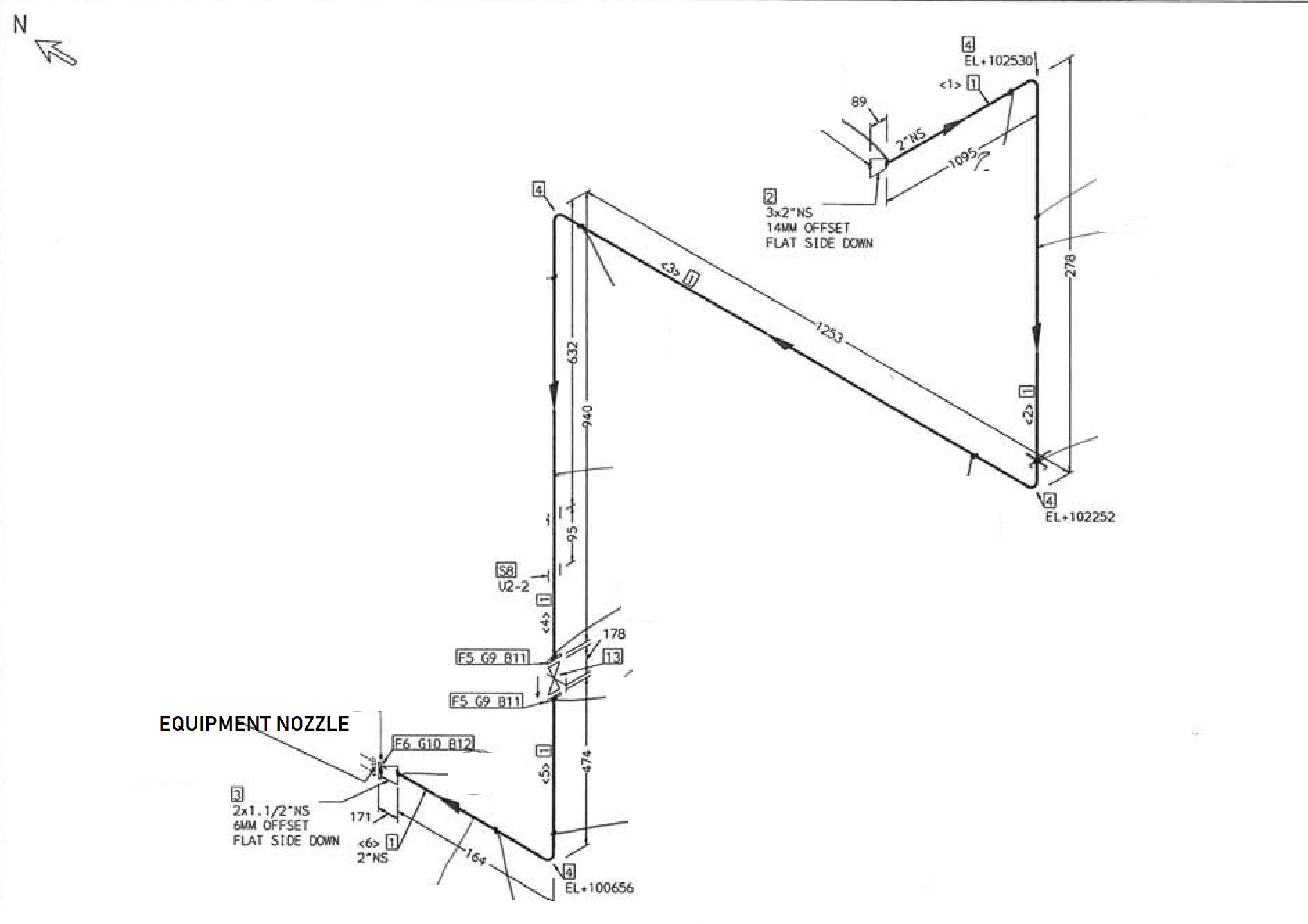
An isometric drawing is drawn with a single line. This single line symbolizes the center of the pipe. And any dimensions shown to it is always center to center of the system. To read Piping isometric drawing you must know the following things:
- Piping Isometric drawing dimensions are always from center to center of pipe.
- Pipe size is always written at any connecting point of Isometric.
- Co-ordinate and Elevation of Pipe is written at connecting points of Piping isometric drawing.
- Material description for Pipe is described in Piping isoemtric drawing on top right corner.
- Rolling in Isometric drawings are shown with Hatches.
- In case of Rolling of pipe, Its conventional direction not remains same to North, South, East or West.
- You must learn symbols of piping components and fittings to know required material for piping system.
- In top Left corner of Isometric considered direction is Indiacated. Normally It is considered North.
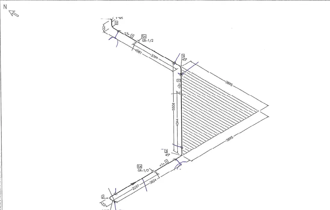
To fully understand and read thoroughly a piping isometric drawing you need to get skills of imagination too. Let’s take an example:
From the above sample isometric, you can easily observe the following:
- The piping system starts with Equipment.
- Pipe line is connected with the equipment via a Socket weld flange of size 1.5″ with an eccentric reducer of size 2″x1.5″.
- After equipment line travel towards South direction and travels in upwards direction.
- A flanged end gate valve is there for which handle direction is towards the south.
- Further routing of Line is towards vertical upwards >> Travel towards south >> Travels vertical upwards >> moves towards west and end with 3″x2″ eccentric reducer.
Sometimes Pipe doesn’t travel towards the exact East, West, North, or South direction. In that case, a Rolling triangle is shown in the isometric drawing which helps us to get a vision of the travel direction of the pipe.
A piping rolling triangle can be of 02 types:
- Horizontal rolling triangle: In this type of rolling pipe take diversion in its direction with respect to a verticle plane.

Here pipe takes a diversion from East to North in the horizontal plane with respect to a verticle plane. - Vertical Rolling triangle: In this type of rolling pipe takes diversion with respect to the horizontal plane.
 In this case, the pipe is moving at some angle from a horizontal plane in the north direction.
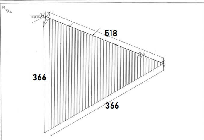
Note: A cloud symbol in pipe isometric drawing indicate revision in that Iso.
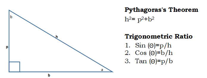
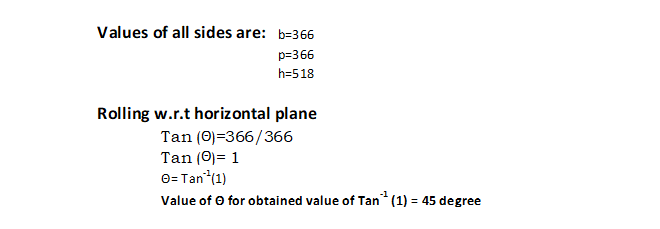
Rolling angle with respect to any plane can be obtained with help of the Pythagoras theorem.
Example of Rolling angle calculation:
Verticle rolling angle from the sample image can be obtained as:
Conclusion
From the above article on learning about piping isometric drawing we can conclude with the following:
- Isometrics are 2D representations of the 3D pipe line.
- Piping isometric gives us information about the Direction of fluid flow, MOC, BOM, Weld joint, Piping fitting, and components, Line no. , Connecting line no. and many more.
- The coordination system for piping is base to calculate pipe length and identify the exact location of the piping system.
- Piping symbols are important to read drawings as it gives quick reference about fittings, joint types, valve types and any other special component to be used.
- When the Pipe doesn’t move in the exact North, South, East, or West direction then the movement is shown with help of rolling angles.
- The rolling angle can be calculated using the Pythagoras theorem and trigonometric ratio.


Thanks For Detailed Explanation 🙂
Thank you for sharing this informative and thought-provoking blog post. It’s clear that you put a lot of time and effort into researching and writing this, and it definitely shows in the quality of the content.Your insights on this issue really hit home for me and I think they will for many other readers as well. Keep up the great work!
Thanks for your inspiring words.
Thanks for your inspiring words.
All of the above is true. Let’s discuss this issue.
WONDERFUL Post.thanks for share…..
Thanks a lot, I really enjoyed the subject as an apprentice pipe fitter. Though one area on reading isometric drawing that gets me a bit on my wit end is reading with the Rolling angles. I wish I could get more insight on that subject. Thanks.
Thanks for your words we will update this article with more on pipe rolling.
Amazingly simple to understand how to read Isometrics. My new colleague also loved it.
Good afternoon Sir
My name is Brian Maart from Cape Town in South Africa. I am working as a Fabrication Supervisor on various projects in and around Cape Town.I am currently busy with some pipework for a company. What I would like to ask you is, that how do I determent the piping specification on a P&ID drawings. Like the specific material of pipe to be used, class of pipe,
The rest I do understand like the valve specs, but only to understand the piping class.
Thank you so much for your website.
Hi Brian,
P&ID drawings don’t give you any specifications related to Piping material. However, this will give you an Isometric drawing no. and you can determine piping material from there.
Thanks for Reading, Plz Keep visiting.
I am also commenting to let you understand of the remarkable discovery my cousin’s princess found reading your web page. She came to understand some things, with the inclusion of what it is like to possess a very effective coaching spirit to make other people very easily understand a variety of tricky subject areas. You actually exceeded our own expectations. I appreciate you for providing these informative, trustworthy, educational and as well as cool guidance on your topic to Julie.
I am piping supervisor
It is Really good to have a reader like you.
Be with us and share your exprience