The No Load Test and Mechanical Run Test of the motor are two critical pre-commissioning procedures utilized to examine the performance and functionality of electric motors in all process industries. These tests hold significant importance in ensuring the reliability and efficiency of the equipment across various applications.
The No Load Test is done to evaluate the motor’s performance when it operates without any external load. During this test, the motor is run without any mechanical load attached, allowing for the measurement of parameters such as idle speed, no-load current, and no-load power consumption. This test aims to determine the motor’s power characteristics, losses, and efficiency under no-load conditions. Also, it is done to identify any unusual vibrations or noise that may occur during operation.
On the other hand, the Mechanical Run Test is performed to examine the motor’s performance under operating conditions with a mechanical load. In this test, the motor is connected to its intended load and operated at various speeds and loads to simulate real-world operating conditions. The primary purpose of this test is to verify the motor’s ability to deliver the required power output, torque, and speed while maintaining stable operation. It enables the detection of potential issues such as excessive heating, abnormal vibrations, or inadequate performance that may arise when the motor is under load.
In this article, we will learn all about the no load test and mechanical run test in brief which determine the performance of overall equipment towards running a processing plant.
Table of Contents
What is No Load test of a motor?
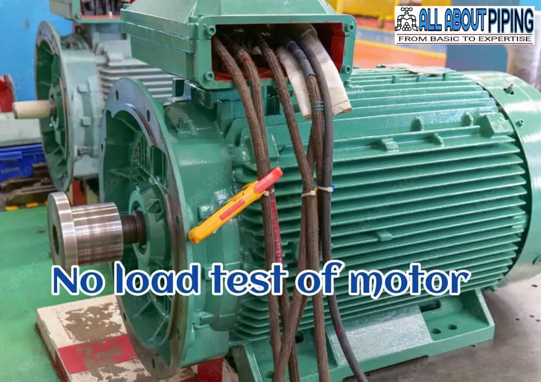
The No Load Test of an electric motor is a procedure to evaluate its performance and characteristics when operating without any external mechanical load. This test aims to measure various parameters of the motor under unloaded conditions.
To conduct the No Load Test, the motor is disconnected from any load and connected directly to a power supply. The power supply is adjusted to provide the motor’s rated voltage and frequency. Once the motor is energized, specialized instruments are used to measure its speed, current, and power consumption.
The No Load Test enables engineers to evaluate important aspects of the motor’s performance as follows:
- No-load current: The amount of current drawn by the motor when operating without any load. This measurement helps assess the motor’s idle power consumption and provides an indication of the efficiency of its electrical components.
- No-load speed: The rotational speed of the motor when it is not driving any load. This parameter reveals the motor’s mechanical characteristics, including its maximum attainable speed and stability.
- No-load power consumption: The amount of electrical power consumed by the motor when operating without a load. This measurement aids in evaluating the motor’s efficiency by assessing its power losses and determining the power required to overcome internal friction and windage.
More readings: Type of Control valve: XV, PV, TV, LV, HV, brief on the working and selection
Theory of No load Test of a Motor
The theory behind the no load test is based on the understanding that when a motor operates without any load connected to its shaft, the power consumed solely accounts for the motor’s internal losses. These losses can be classified into two main types:
- Iron losses (also known as core losses or no-load losses): These losses arise due to the magnetization and demagnetization of the motor’s core as the magnetic field alternates. They encompass hysteresis losses and eddy current losses.
- Hysteresis losses: These losses occur as a result of the core material repeatedly magnetizing and demagnetizing when the magnetic field changes direction. This phenomenon leads to energy losses due to molecular friction within the core material.
- Eddy current losses: These losses materialize due to the circulating currents induced in the core material by the alternating magnetic field. The eddy currents cause resistive heating and result in energy losses.
- Mechanical losses: These losses primarily stem from friction and windage within the motor. Friction losses manifest in the motor bearings, brushes (in the case of brushed motors), and other moving parts. Windage losses arise due to the resistance encountered by the rotating motor components in the surrounding air.
During the no-load test, the motor operates at its rated voltage while the shaft remains free to rotate without any external load. Measurements are taken for the input power, current, and voltage, while the output power is negligible since no load is present. Consequently, the input power corresponds to the losses within the motor.
Using the measured values, various parameters can be calculated, including the no-load current (which represents the core losses), the no-load power (which indicates the total losses), and the rotational speed (which approximates the synchronous speed of the motor).
More to Read: Falling film evaporator: Design, Working, Features and Application
testing tools used for No load test (NLT)
Several testing equipment and instruments are commonly used for conducting a no load test on motors. Here are some essential tools and equipment used in the no-load testing process:
- Multimeter
- Tachometer
- Power Analyzer
- Temperature Sensor
- Data Logger
It’s important to note that the specific testing equipment and instruments used may vary depending on the motor type, size, and the desired level of precision required for the test. Additionally, adherence to relevant industry standards and guidelines is crucial when selecting and using testing equipment for the no-load test.
Procedure of No load test of motor
The no-load test procedure for a pump involves the following steps:
- Preparation: Ensure that the pump is installed correctly and securely, with all necessary connections and fittings in place. Verify that the pump is properly primed.
- Safety Check: Ensure that all safety measures are in place, such as protective guards, emergency stop buttons, and proper ventilation. Follow all safety protocols and use appropriate personal protective equipment (PPE) when operating the pump.
- Power Supply: Connect the pump to a suitable power supply, ensuring compliance with electrical requirements and safety regulations. Check that the power supply is stable and within the specified voltage and frequency range.
- Start-Up: Switch on the pump motor using the appropriate controls or switchgear. Allow the pump to reach a stable operating condition, ensuring that the motor is running smoothly.
- No Load Condition: De-couple the motor and impeller part of the pump for rotation of the motor without any load.
- Performance Monitoring: Measure and record various parameters during the pump operation, such as power consumption, rotational speed, and input current. Use appropriate instruments and sensors to obtain accurate readings of these parameters.
- Duration: Run the motor under the no-load condition for a sufficient duration to gather reliable data and stabilize the measurements. The duration can vary depending on the specific requirements or industry standards.
- Data Analysis and Evaluation: Analyze the recorded data and compare the pump’s performance against the specified requirements and expected values. Evaluate the pump’s power consumption, rotational speed, input current, and any deviations or issues observed during the test.
- Shut Down: Once the test is completed, switch off the pump motor and disconnect the power supply. Allow the pump to cool down if needed, following the manufacturer’s recommendations.
- Documentation: Preparing a report for No load test is as important as executing this activity. Prepare a detailed report documenting the no-load test procedure, measurements, observations, and any identified issues or recommendations. Maintain the test report as part of the pump’s records for future reference or comparison.
As with any test procedure, it’s important to consult the manufacturer’s instructions and guidelines specific to the pump being tested. Additionally, ensure that the test is conducted by qualified personnel adhering to relevant safety protocols and regulations.
Acceptance criteria of No load test
The acceptance criteria for a no-load test may vary depending on the specific motor or industry standards. However, there are several common factors considered for evaluating the results of a no-load test. These factors include:
- No-Load Current: The measured no-load current should fall within the specified range provided by the motor manufacturer. Excessive no-load current may suggest issues with winding insulation, rotor condition, or core saturation.
- Power Factor: The power factor of the motor during the no-load test should meet the specified limits. A low power factor can result in increased energy consumption and inefficient operation.
- Core Losses: The measured core losses should be within the acceptable range. Core losses contribute to energy dissipation and can impact motor efficiency. Excessive core losses may indicate problems with the motor’s magnetic circuit or laminations.
- No-Load Speed: The measured no-load speed should closely approximate the motor’s synchronous speed. Deviations from the synchronous speed may indicate mechanical issues or incorrect motor connections.
- Temperature Rise: The motor’s temperature rise during the no-load test should not exceed the specified limits. Excessive temperature rise can indicate problems with cooling, such as inadequate ventilation or blocked air passages.
- Voltage Variation: The voltage supplied to the motor during the no-load test should remain stable and within the specified voltage range. Fluctuations in voltage can affect motor performance and may indicate issues with the power supply or voltage regulation.
- Sound and Vibration: The motor should operate smoothly with minimal noise and vibration during the no-load test. Excessive noise or vibration may indicate mechanical imbalances, misalignment, or bearing issues.
Apart from the above, it is always important to look for the criteria provided by the manufacturer to determine the precise acceptance of the No load test. All the criteria may vary according to the size of the motor, Its type and application.
More to read: 1G, 2G, 3G Bioethanol: What are different Bioethanol generation technologies?
What is mechanical run test?
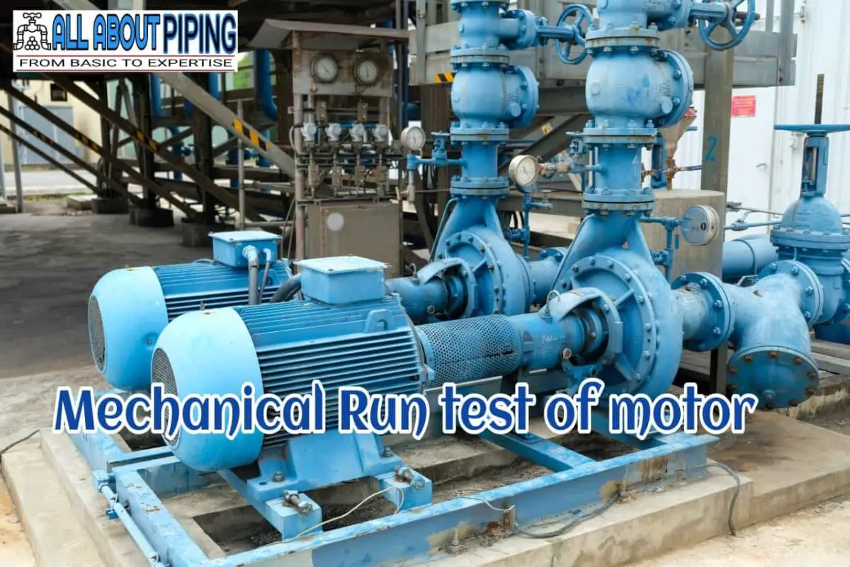
The mechanical run test of a pump is a stage of the pre-commissioning procedure to be carried out to assess the performance and mechanical characteristics of the pump under real-world operating conditions. It entails operating the pump with a mechanical load applied to the motor according to its general operating condition.
The primary objective of the test is to evaluate multiple factors, including the behaviour during start-up and shutdown, flow and pressure performance, efficiency, vibration and noise levels, temperature, sealing effectiveness, and overall functionality. By conducting the mechanical run test, engineers can validate the pump’s performance, identify any issues or deviations, and ensure its effective and reliable operation prior to its deployment.
Theory of Mechanical Run Tests
The basic theory behind doing a mechanical run test of a pump is to determine if the motor designed is giving exact same performance as it is intended to do. During the mechanical run test few characteristics are to be observed as follows:
- Net Pressure Discharge Head: Net Pressure Discharge Head (NPDH) refers to the total pressure available at the discharge outlet of a pump. It is important in determining the pump’s ability to deliver the desired flow rate and pressure to the intended destination.
- Leakage and Sealing Evaluation: For pump handling fluids, the test is important for assessing the presence of leaks or evaluating the effectiveness of seals and gaskets to ensure proper sealing and prevent fluid leakage.
- Temperature Monitoring: The temperature of various pump components, such as bearings, seals, or motor windings, may be monitored during the test. Elevated temperatures can indicate insufficient cooling or potential mechanical problems that may impact the pump’s reliability.
- Vibration and Noise Analysis: Vibration levels and noise produced by the pump during operation are monitored. Excessive vibration or noise may indicate mechanical imbalances, misalignment, or issues with bearings or other components that could affect the pump’s performance and reliability.
Testing equipment used for Mechanical run test (MRT)
Many testing instruments are commonly used for the mechanical run test of a motor. These instruments used for evaluating the motor’s performance, mechanical characteristics, and operational parameters. Some of the typical testing instruments used for the mechanical run test of a motor include:
- Tachometer: A tachometer is used to measure the motor’s rotational speed or RPM (Revolutions Per Minute) during the test. It provides an accurate reading of the motor’s actual speed and helps verify if it is operating within the desired range.
- Dynamometer: A dynamometer is an instrument used to measure the torque produced by the motor. It allows for the assessment of the motor’s mechanical output and can provide insights into its power and efficiency.
- Vibration Analyzer: A vibration analyzer is employed to measure and analyze the vibrations generated by the motor. It helps identify any abnormal vibrations that may indicate mechanical imbalances, misalignment, or issues with bearings or other components.
- Temperature Sensors: Temperature sensors or thermocouples are used to measure the temperature of various motor components such as windings, bearings, or cooling systems. Monitoring temperature is essential to ensure that the motor operates within safe limits and to identify any overheating issues.
- Power Analyzer: A power analyzer is used to measure and analyze electrical parameters such as voltage, current, and power consumption of the motor during the mechanical run test. It provides insights into the motor’s electrical performance and energy efficiency.
- Load Bank: A load bank is used to apply an artificial electrical load to the motor during the test. It allows for the simulation of real-world operating conditions and helps assess the motor’s performance under different load scenarios.
- Data Acquisition System: A data acquisition system is utilized to collect, record, and analyze data from various sensors and instruments during the mechanical run test. It enables the capture of precise measurements and facilitates data analysis for performance evaluation.
These testing instruments assist in obtaining accurate measurements and data during the mechanical run test of a motor, enabling engineers to evaluate its performance, diagnose issues, and ensure its optimal functioning in real-world applications.
More to read: Type and Selection of Hydraulic Oil
Procedure for Mechanical run test
The procedure for the Mechanical Run Test of a Pump involves the following as described below:
- No load Test: Before proceeding to the Mechanical run test it is important to check if the No-load test has been done on the motor or not. After completion of the No-load test, only MRT should be carried out.
- Start-Up: a. Switch on the pump motor using the appropriate controls or switchgear and allow the pump to reach a stable operating condition, ensuring that the motor and pump are running smoothly.
- Mechanical Run Test: Gradually increase the flow rate or discharge pressure according to the pump’s design and operating conditions. Observe the pump’s performance, including factors such as vibration, noise, temperature, and pressure fluctuations. Also, Monitor and record relevant parameters, such as flow rate, discharge pressure, suction pressure, and motor current. Check for any leaks, abnormal noises, or unusual vibrations during the test.
- Performance Monitoring: Continuously measure and record various parameters during the mechanical run test, such as power consumption, rotational speed, and temperature using appropriate instruments.
- Duration: Run the pump under normal operating conditions for a sufficient duration to gather reliable data and stabilize the measurements. The duration can vary depending on the specific requirements or industry standards.
- Data Analysis and Evaluation: Analyze the recorded data and compare the pump’s performance against the specified requirements and expected values. Evaluate the pump’s efficiency, power consumption, temperature rise, vibration levels, and any deviations or issues observed during the test.
- Shut Down: Once the mechanical run test is completed, switch off the pump motor and disconnect the power supply.
- Documentation: Prepare a detailed report documenting the mechanical run test procedure, measurements, observations, and any identified issues or recommendations and preserve it for future usage.
Acceptance criteria for Mechanical run test
The acceptance criteria for a mechanical run test may vary depending on the specific requirements and standards set by the industry or the manufacturer. However, here are some general acceptance criteria commonly considered during a mechanical run test:
- Stable Operation: The pump should be stable operation without any sudden fluctuations, abnormal vibrations, or excessive noise. It should run smoothly and continuously without any interruptions or significant deviations from expected behaviour.
- Flow and Pressure Performance: The pump should be able to deliver the specified flow rate and pressure within an acceptable tolerance range. The measured values should align with the design requirements or performance specifications provided by the manufacturer.
- Efficiency: The pump’s efficiency should be within the acceptable range, indicating how effectively it converts mechanical power into fluid energy.
- Temperature: The temperature rise of critical components, such as bearings and windings, should remain within the specified limits. Excessive temperature elevation may indicate issues with cooling, lubrication, or mechanical problems that could affect the pump’s reliability and lifespan.
- Leakage: The pump should not exhibit any significant leaks or abnormal fluid losses. The seals and gaskets should effectively prevent fluid leakage, ensuring the pump operates as intended.
- Mechanical Integrity: The pump’s mechanical components, including the shaft, impeller, and couplings, should demonstrate proper alignment and balance. There should be no excessive vibrations, abnormal noise, or visible signs of mechanical stress during the test.
Mechanical run tests should be determined based on the specific requirements and guidelines provided by the manufacturer or relevant standards in the industry. These criteria ensure that the pump meets the necessary performance standards and can be considered acceptable for its intended application.
Difference between No load test and Mechanical run test (NLT vs MRT)
The main difference between the no load test and the mechanical run test lies in the operating conditions under which the tests are conducted. Here are the few main difference between the two:
| SL. No. | Aspects | No Load Test | Mechanical Run test |
|---|---|---|---|
| 01 | Purpose | Evaluate performance characteristics under no load | Assess overall performance under operating conditions |
| 02 | Load Condition | No load | Operating conditions with the fluid being pumped |
| 03 | Measurements | Power consumption, rotational speed, input current | Flow rate, pressure, power consumption, efficiency, temperature, motor current, etc. |
| 04 | Validation | Establish baseline values, diagnose potential issues | Validate performance, functionality, and mechanical reliability |
| 05 | Focus | Electrical characteristics of the pump motor | Overall pump performance and mechanical integrity |
| 06 | Resistance/Pressure | No resistance or load applied to the pump output | Operating under specified resistance/pressure conditions |
Difference between Mechanical run test and performance test
The mechanical run test and the performance test of a pump are two distinct evaluations conducted to assess different aspects of the pump’s operation. Here are the key differences between the two tests:
| SL. No. | Aspect | Mechanical Run Test | Performance Test |
|---|---|---|---|
| 01 | Purpose | Assess mechanical behaviour and performance | Evaluate hydraulic performance and efficiency |
| 02 | Load | A mechanical load applied to simulate real operating conditions | Controlled flow rates and pressures |
| 03 | Mechanical characteristics and behaviour | Start-up and shutdown behavior, vibration levels, noise, temperature rise, sealing effectiveness, mechanical functionality | Actual flow rate, pressure, power consumption, efficiency |
| 04 | Acceptance Criteria | Stable operation, flow and pressure performance, temperature rise, leakage, mechanical integrity, compliance with standards | Meeting specified flow rate, pressure, and efficiency requirements |
| 05 | Test Environment | Real-world operating conditions | Controlled testing conditions |
| 06 | Focus | Start-up and shutdown behaviour, vibration levels, noise, temperature rise, sealing effectiveness, mechanical functionality | Hydraulic performance and efficiency |
Conclusion
In summary, No Load Test:
- Evaluates core loss in electrical machines.
- Measures power and current without external load.
- Determines core losses and efficiency.
- Provides insights for magnetic circuit design.
Mechanical Run Test:
- Assesses mechanical behaviour of equipment.
- Operates under real-world conditions with a load.
- Evaluates stability, vibration, temperature, and integrity.
- Ensures smooth and reliable operation.
The no load test focuses on core losses and efficiency in electrical machines, while the mechanical run test assesses the mechanical performance of equipment. Both tests play crucial roles in optimizing functionality and reliability in their respective domains.


Useful article, thank you. Top article, very helpful.