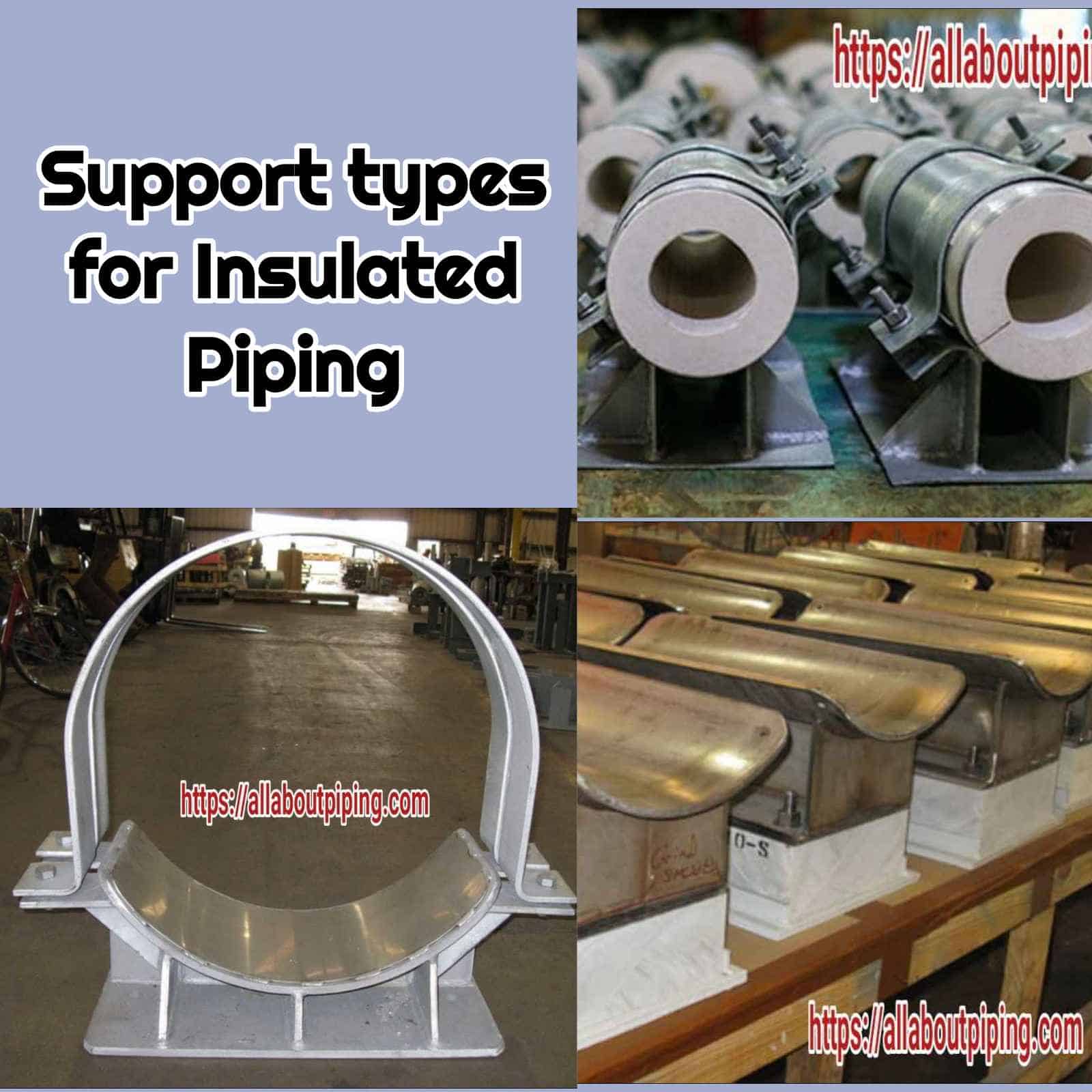
Piping Support system changes with a requirement of Insulation. While a wear pad is enough to rest on structure for Non-insulated Pipes, A shoe of Saddle support is required for giving space for insulation to insulated Piping.
Pipe supports for Insulated Line are designed to prevent direct heat transfer either from environment to Pipe or Pipe to environment. So, they help to reduce heat loss due to conduction. Here in this Article of “Piping Supports as Per Insulation System” you will learn the following:
- Need of Insulated Pipe supports
- Types of Insulated Pipe supports
- Brief about Pipe Support for hot insulation.
- Details of Pipe Supporting for Cold insulation or Cryogenic Supports
- Installation details of Non-insulated Pipe Supports.
More to Read: Heat Tracing in Piping: Types, Working, Use, Installation, Comparison
Table of Contents
Need of Insulated Pipe Supports
An insulated line has different sets of Support system which help to pipe network to:
- Direct contact from structural or civil part of Project.
- Provide space for insulation material installation.
- Withstand with load of pipes.
- Stop heat loss or heat gain.
Types of Support as Insulation System
For supporting pipe with insulation support required are different from normal supports as of bare pipes or non-insulated pipes. Supports that are used for Insulated lines are:
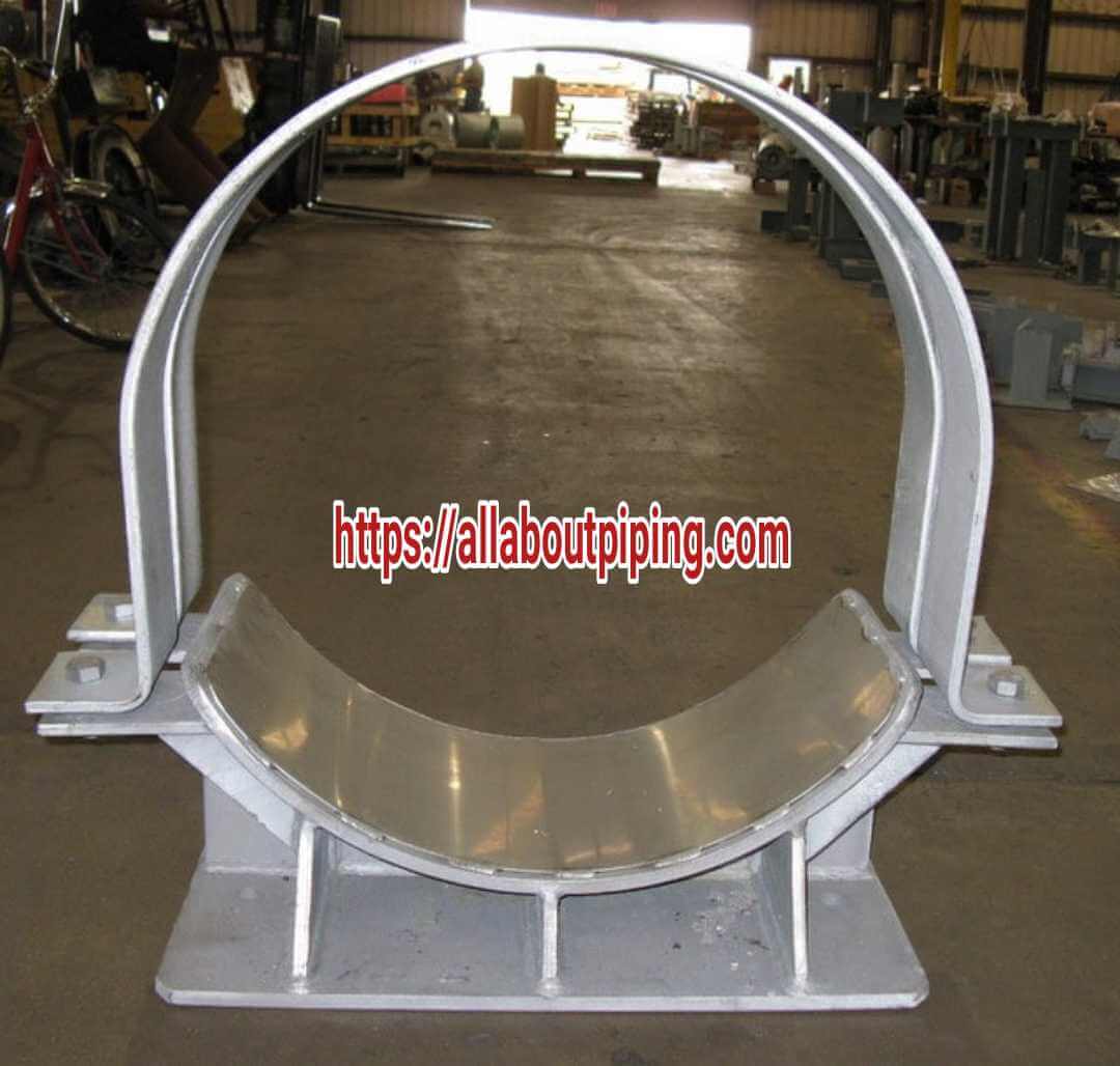
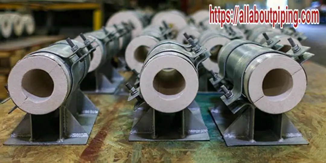
- Clamp Shoe or Saddle Supports: As the name specifies, these types of support are clamped with pipes instead of welding.
- Welded shoe or saddle support: These supports are directly welded with a pipe. An RF pad of 120º cut is attached above shoe or saddle support.
- Cryogenic supports These specially designed supports used for cold insulated lines. Puf density here is designed to take the load of pipe.
Piping Supports for Hot insulated Pipes
Supports for hot insulated lines should have followed these procedures for effective heat arrest:
- Insulated pipes shall not rest directly on their insulation but have pipe shoes applied.
- Cradles and pipe shoes of pipes operating at temperatures above 400 °C (750 °F) used to be insulated from the supporting structure by incombustible insulating blocks of sufficient load-bearing and insulation capabilities with the following exception when the installation of clamped cradles or pipe shoes around the insulation shall be subject to approval by the Client.
- The design of pipe supports for hot insulated pipes shall be in accordance with the thermal insulation details.
Saddle or shoe support design must include some basic details as follows:
- 6mm holes at two positions 100mm apart must be provided for the insulation band to flush insulation thickness.
- In General practice, the Height of Shoe or saddle support should 50mm greater than the insulation thickness of the pipe.
- For small bore hot insulation supports, clamped type support should be used to avoid distortion in the straightness of the pipe.
- An RF pad of the same pipe material of 120º cut should be installed to saddle which is further welded to the pipe. It is advised to avoid welding of saddle or shoe support directly on the pipe.
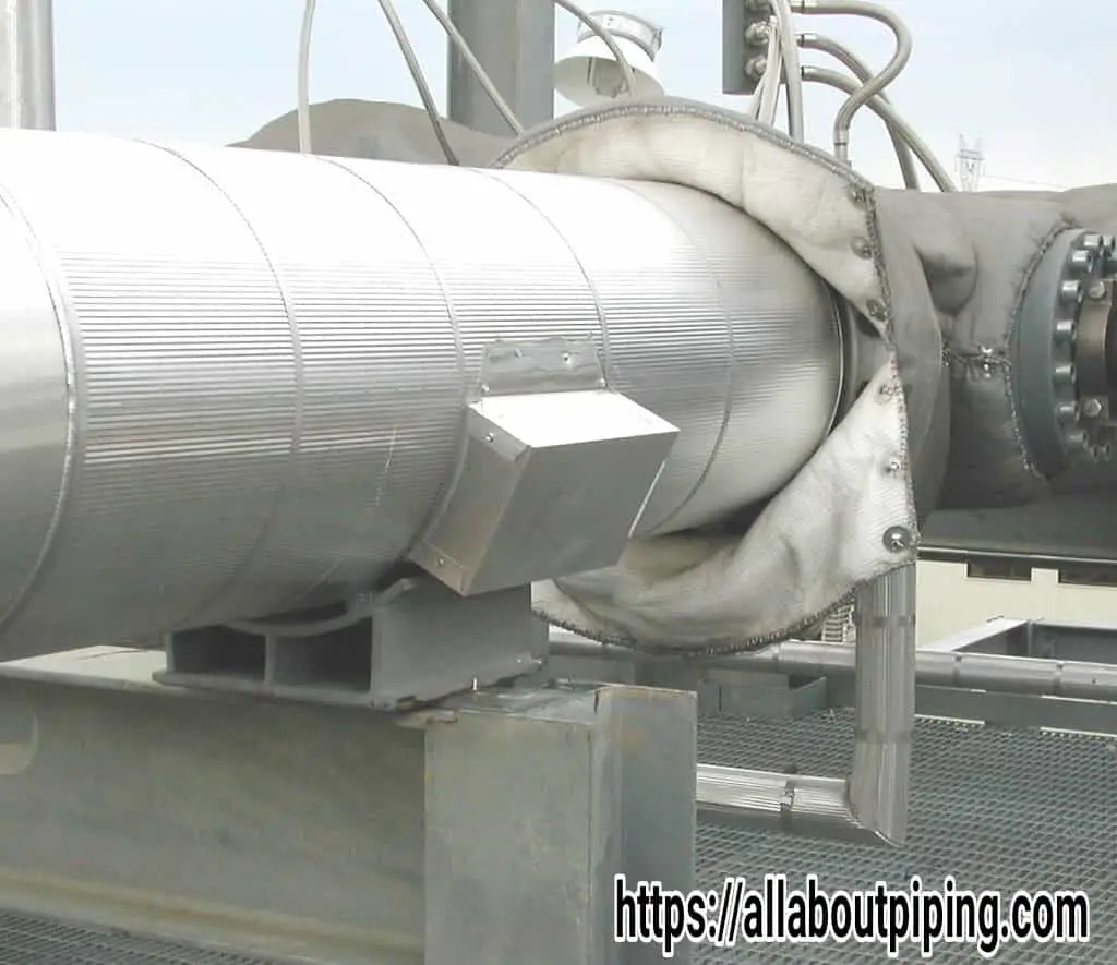
Piping Supports for Cold insulated Pipes
For cold insulated supports specially designed and fabricated supports are required which can bear the load of pipes as well as provide a barrier of heat gain from the environment. Support for cold insulation support is made from:
- High-Density Polyurethane Foam
- Phenolic foam insulation
- Polyisocyanurate or PIR
These all types of material provide rigid support towards the cryogenic condition of a piping system. During the installation of these supports following things need to follow for beneficial advantages of cryogenic supports:
- Pipe supports for cold-insulated pipes shall be clamped to the outer surface of the insulation system in order to avoid the ingress of moisture in the insulation.
- Temporary protection should be provided during installation to prevent the ingress of moisture.
- At locations where field insulation is applied (e.g., around field welds), the insulation should be installed after pressure testing the pipe.
- Since the pipe supports are required during erection and testing of the piping, It is advisable that insulation should be installed after erection and testing the pipe.
- The clearance between the insulation and the supporting structure should be at least 50 mm as per normal practice which should take into account for movements of the pipe caused by thermal expansion/contraction.
- At sliding points, the loads due to friction should be checked against the load-bearing capacity of the insulation. If required, sliding plate assembly should be fitted between the pipe shoe and supporting member.
- The forces and moments on anchors, pipe stops, and rotating supports should be checked.
- Where welded attachments are used, the pipe supports shall be insulated from these attachments using laminated hardwood or solid resin blocks of sufficient load-bearing capacity and insulation properties.
Piping Supports for Non-Insulated Pipes
Some of the major points for Non-insulated Pipe support installation are as follows:
- Pipe shoes should be used where the pipe can operate (even temporarily) at such a low temperature as to cause embrittlement of the supporting member.
- Pipe shoes should be used for the following:
a. Pipes with sizes larger than DN 600 (NPS 24);
b. Carbon steel pipes with a wall thickness less than schedule 20;
c. Stainless steel pipes with a wall thickness less than schedule 10S;
d. The pipe requires a slope. This is only for small slope corrections. - In others cases, other non-insulated pipes should rest directly on the supporting steel.
- Where pipe shoes are used to support sloping pipe, the height of pipe shoes measured from the underside of the pipe shall be a maximum of 400 mm (16 in).
- For piping systems where only small forces on supports can be expected (e.g., instrument air systems), U-bolts may be used.
- This can apply to small-bore piping typically DN50 (NPS 2) and below.
- U-bolts shall not be used as fixed points because their grip is not reliable and damages the coating system.
- If composite sleeves are applied, they shall be designed and installed so that water cannot penetrate under the sleeve. Movements of pipes by thermal expansion/contraction can cause damage to the paint, and therefore corrosion, at the location of the supports and guides. This damage can be avoided by protecting the pipe with a composite sleeve at the location of the support.
